* Signalling protocol options are dependent on the communication module installed
In accordance with EN50131-6:2017, the control panel standby times and effective output currents depend on the Security Grade of the system and how mains missing fault is signalled to the Alarm Receiving Centre. Power supplies are rated in accordance with the requirements of EN50131-6, which are related to the maximum battery size that can be accommodated in the housing and vary according to the grade of the system in which they are installed, as per the following table.
Zones |
Outputs |
|||||
Device |
RS-485 Address |
Maximum allocation |
Zone Numbers |
Maximum allocation |
Total Number of Outputs |
|
First |
Last |
|||||
| Endstation | N/A | 8 | 1 | 8 | 6 | 6 |
| ATE | N/A | N/A | N/A | N/A | 10 | 16 |
| Bell | N/A | N/A | N/A | N/A | 3 | 19 |
| Wireless bell outputs | N/A | N/A | N/A | N/A | 4 | 23 |
| Zone expansion module | 0 | 8 | 9 | 16 | 4 | 27 |
| Zone expansion module | 1 | 8 | 17 | 24 | 4 | 31 |
| Zone expansion module | 2 | 8 | 25 | 32 | 4 | 35 |
| Zone expansion module | 3 | 8 | 33 | 40 | 4 | 39 |
| Zone expansion module | 4 | 8 | 41 | 48 | 4 | 43 |
| Zone expansion module | 5 | 8 | 49 | 56 | 4 | 47 |
| Zone expansion module | 6 | 8 | 57 | 64 | 4 | 51 |
| Zone expansion module | 7 | 8 | 65 | 72 | 4 | 55 |
| Zone expansion module | 8 | 8 | 73 | 80 | 4 | 59 |
| Zone expansion module | 9 | 8 | 81 | 88 | 4 | 63 |
| Zone expansion module | 10 | 8 | 89 | 96 | 4 | 67 |
| Zone expansion module | 11 | 8 | 97 | 104 | 4 | 71 |
| Zone expansion module | 12 | 8 | 105 | 112 | 4 | 75 |
| Zone expansion module | 13 | 8 | 113 | 120 | 4 | 79 |
| Zone expansion module | 14 | 8 | 121 | 128 | 4 | 83 |
| Zone expansion module | 15 | 8 | 129 | 136 | 4 | 87 |
| Zone expansion module | 16 | 8 | 137 | 144 | 4 | 91 |
| Zone expansion module | 17 | 8 | 145 | 152 | 4 | 95 |
| Zone expansion module | 18 | 8 | 153 | 160 | 4 | 99 |
| Zone expansion module | 19 | 8 | 161 | 168 | 4 | 103 |
| Zone expansion module | 20 | 8 | 169 | 176 | 4 | 107 |
| Zone expansion module | 21 | 8 | 177 | 184 | 4 | 111 |
| Zone expansion module | 22 | 8 | 185 | 192 | 4 | 115 |
| Zone expansion module | 23 | 8 | 193 | 200 | 4 | 119 |
| Zone expansion module | 24 | 8 | 201 | 208 | 4 | 123 |
| Zone expansion module | 25 | 8 | 209 | 216 | 4 | 127 |
| Zone expansion module | 26 | 8 | 217 | 224 | 4 | 131 |
| Zone expansion module | 27 | 8 | 225 | 232 | 4 | 135 |
| Zone expansion module | 28 | 8 | 233 | 240 | 4 | 139 |
| Zone expansion module | 29 | 8 | 241 | 248 | 4 | 143 |
| Keypad or proximity reader | 0 | 2 | 249 | 250 | 2 | 145 |
| Keypad or proximity reader | 1 | 2 | 251 | 252 | 2 | 147 |
| Keypad or proximity reader | 2 | 2 | 253 | 254 | 2 | 149 |
| Keypad or proximity reader | 3 | 2 | 255 | 256 | 2 | 151 |
| Keypad or proximity reader | 4 | 2 | 257 | 258 | 2 | 153 |
| Keypad or proximity reader | 5 | 2 | 259 | 260 | 2 | 155 |
| Keypad or proximity reader | 6 | 2 | 261 | 262 | 2 | 157 |
| Keypad or proximity reader | 7 | 2 | 263 | 264 | 2 | 159 |
| Keypad or proximity reader | 8 | 2 | 265 | 266 | 2 | 161 |
| Keypad or proximity reader | 9 | 2 | 267 | 268 | 2 | 163 |
| Keypad or proximity reader | 10 | 2 | 269 | 270 | 2 | 165 |
| Keypad or proximity reader | 11 | 2 | 271 | 272 | 2 | 167 |
| Keypad or proximity reader | 12 | 2 | 273 | 274 | 2 | 169 |
| Keypad or proximity reader | 13 | 2 | 275 | 276 | 2 | 171 |
| Keypad or proximity reader | 14 | 2 | 277 | 278 | 2 | 173 |
| Keypad or proximity reader | 15 | 2 | 279 | 280 | 2 | 175 |
| Keypad or proximity reader | 16 | 0 | N/A | N/A | 2 | 177 |
| Keypad or proximity reader | 17 | 0 | N/A | N/A | 2 | 179 |
| Keypad or proximity reader | 18 | 0 | N/A | N/A | 2 | 181 |
| Keypad or proximity reader | 19 | 0 | N/A | N/A | 2 | 183 |
| Keypad or proximity reader | 20 | 0 | N/A | N/A | 2 | 185 |
| Keypad or proximity reader | 21 | 0 | N/A | N/A | 2 | 187 |
| Keypad or proximity reader | 22 | 0 | N/A | N/A | 2 | 189 |
| Keypad or proximity reader | 23 | 0 | N/A | N/A | 2 | 191 |
| Keypad or proximity reader | 24 | 0 | N/A | N/A | 2 | 193 |
| Keypad or proximity reader | 25 | 0 | N/A | N/A | 2 | 195 |
| Keypad or proximity reader | 26 | 0 | N/A | N/A | 2 | 197 |
| Keypad or proximity reader | 27 | 0 | N/A | N/A | 2 | 199 |
| Keypad or proximity reader | 28 | 0 | N/A | N/A | 2 | 201 |
| Keypad or proximity reader | 29 | 0 | N/A | N/A | 2 | 203 |
| Output expansion module | 0 | N/A | N/A | N/A | 16 | 219 |
| Output expansion module | 1 | N/A | N/A | N/A | 16 | 235 |
| Output expansion module | 2 | N/A | N/A | N/A | 16 | 251 |
| Output expansion module | 3 | N/A | N/A | N/A | 16 | 267 |
| Output expansion module | 4 | N/A | N/A | N/A | 16 | 283 |
| Output expansion module | 5 | N/A | N/A | N/A | 16 | 299 |
| Output expansion module | 6 | N/A | N/A | N/A | 16 | 315 |
| Output expansion module | 7 | N/A | N/A | N/A | 16 | 331 |
| Output expansion module | 8 | N/A | N/A | N/A | 16 | 347 |
| Output expansion module | 9 | N/A | N/A | N/A | 16 | 363 |
| Output expansion module | 10 | N/A | N/A | N/A | 16 | 379 |
| Output expansion module | 11 | N/A | N/A | N/A | 16 | 395 |
| Output expansion module | 12 | N/A | N/A | N/A | 16 | 411 |
| Output expansion module | 13 | N/A | N/A | N/A | 16 | 427 |
| Output expansion module | 14 | N/A | N/A | N/A | 16 | 443 |
| Output expansion module | 15 | N/A | N/A | N/A | 16 | 459 |
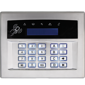 Arming Devices
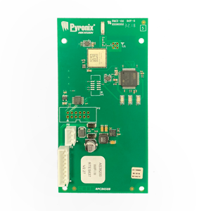 Communication Devices
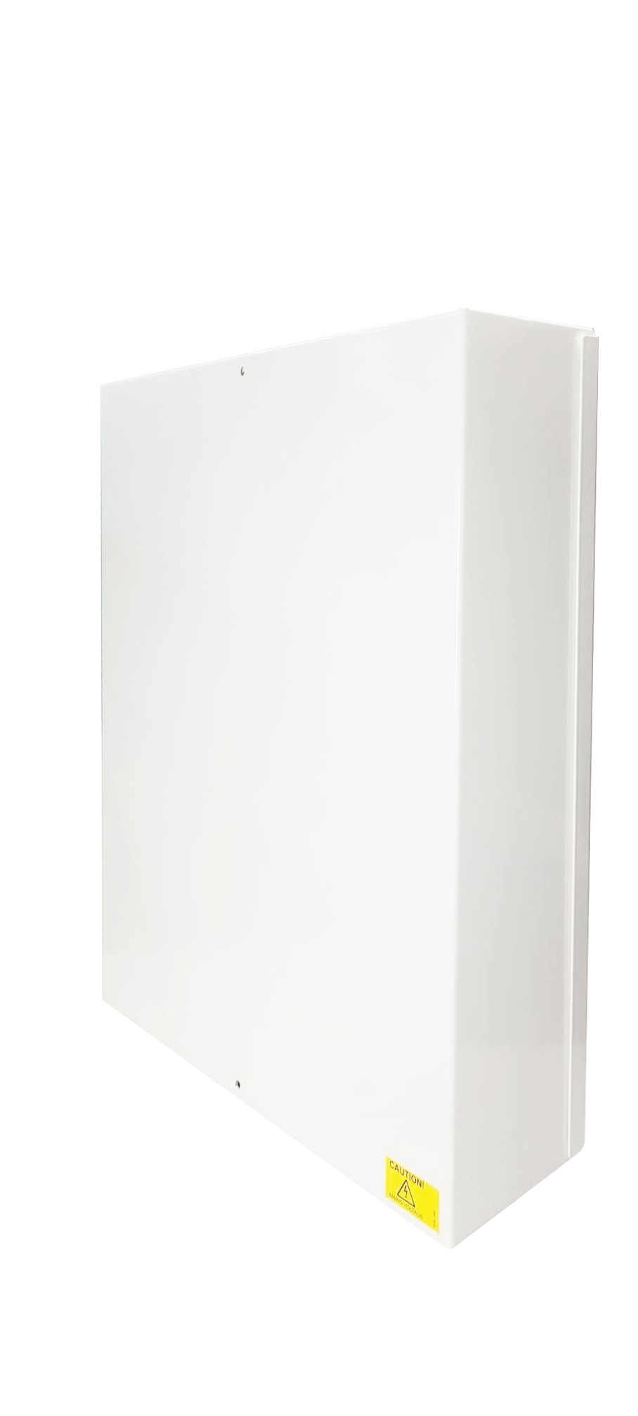
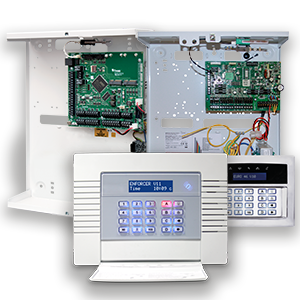 Control Panels
 Detectors & Sensors
 Expanders
 International Products
 Legacy Products
 Smart Home Devices
 Software & Services
 Sounders & Bells
 Speech Diallers
 Wi-Fi Cameras

