Connects the main PCB to the tamper switch on the metal housing of the endstation.
The ATE PGMs are connected to a third party signalling device in order to power the device and to send signals to a monitoring station.
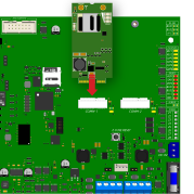
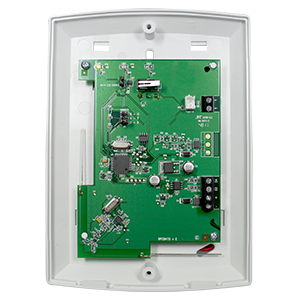
The communication module slots can accommodate any two of the following modules:
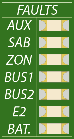
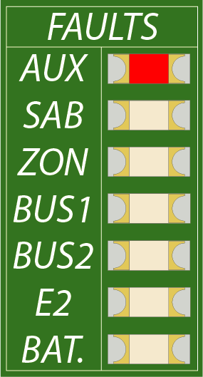
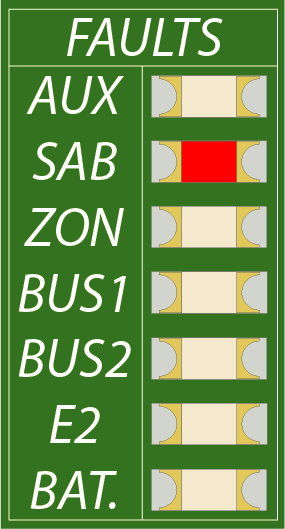
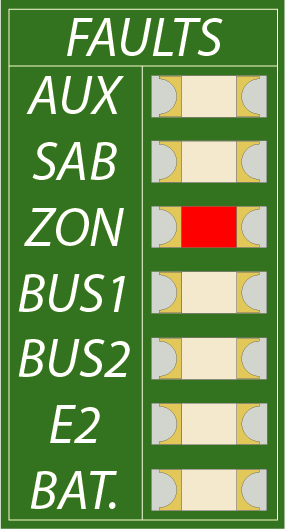
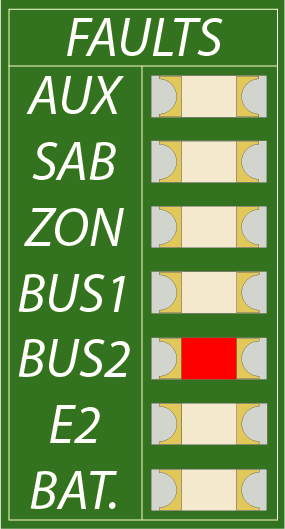
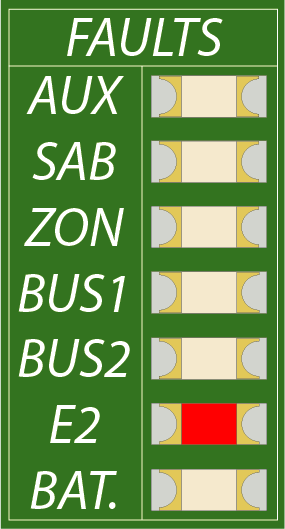
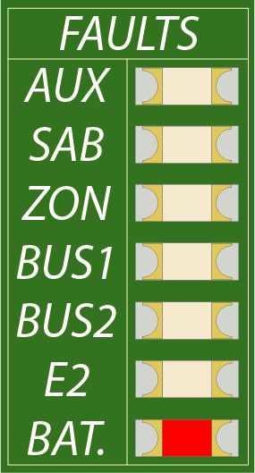
The Endstation LEDs indicate the status of the following:
Once connected via a LAN cable to a network, it can be used to signal via IP to a central station or to communicate with InSite Pro Cloud. It can also be connected to directly with a PC/laptop for an InSite Pro Local connection.
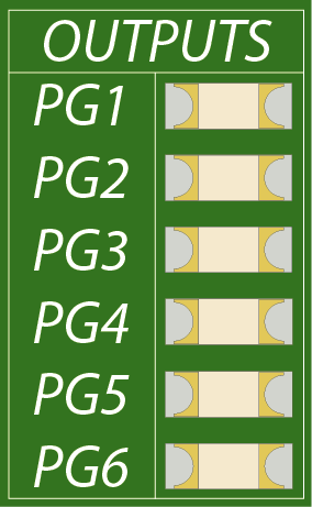
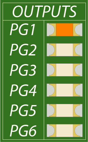
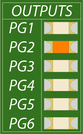
There are two clean relays on the board and 4 transistorised outputs.
The 2 relay outputs are rated at 3A@30VDC each. Both relays have a 3-pin jumper which can be used to apply a voltage to the common of the relay. Placing a jumper linking the top two will make the common 12VDC and when the bottom two are linked, the common will be 0VDC.
The 4 transistorised outputs are rated 200mA@12VDC each and can operate in four different modes:
| Output Polarity Option | Restore State | Triggered State |
| [0] 12v Removed | 12v | Nothing |
| [1] 0v Removed | 0v | Nothing |
| [2] 12v Applied | Nothing | 12v |
| [3] 0v Applied | Nothing | 0v |
Resets all the electronic fuses on the board if any of them have tripped. (The fuses can also be reset through the engineer menu).
Connects the incoming power to the endstation. Click here for power supply specifications.
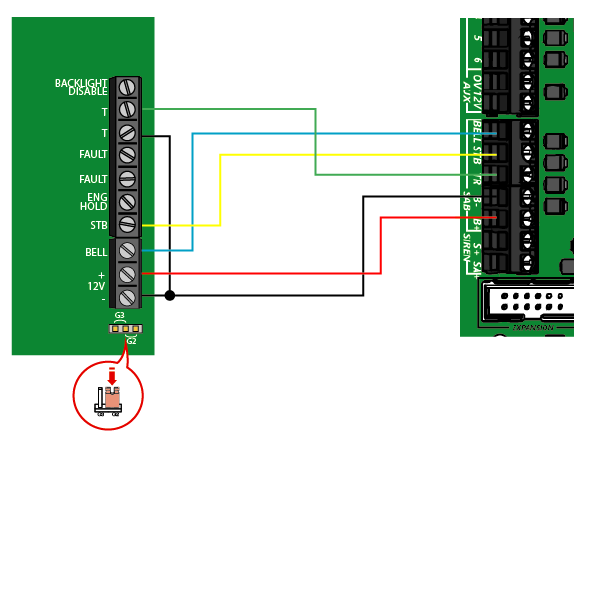
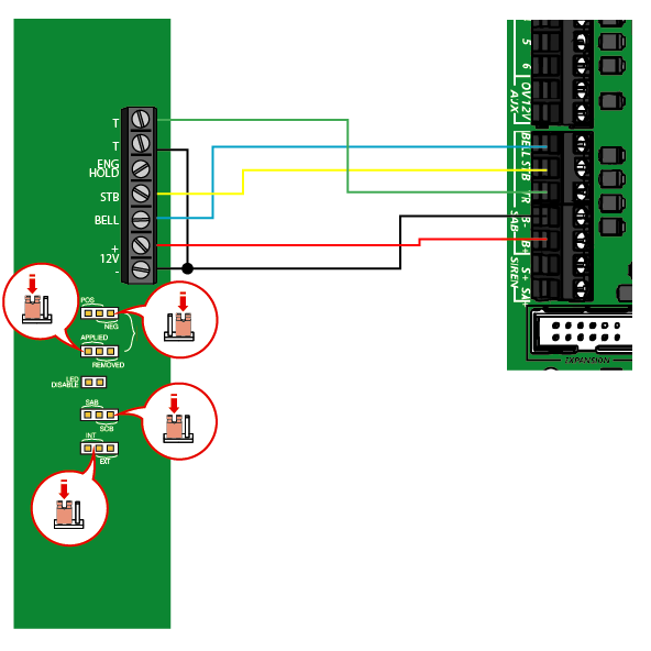
Terminals for wiring an external bell to the control panel. Click here for external bell wiring.
Is used to connect a temporary engineer keypad to.
Sit in between the PCB components and the battery to protect the board and battery from issues such as reverse polarity.
For future use.
The USB port can be used for the following features:
Forces the relay that connects and disconnects the battery circuit to switch and connect the battery to the endstation. This is particularly useful to power up the endstation when there is no incoming mains supply to the panel.
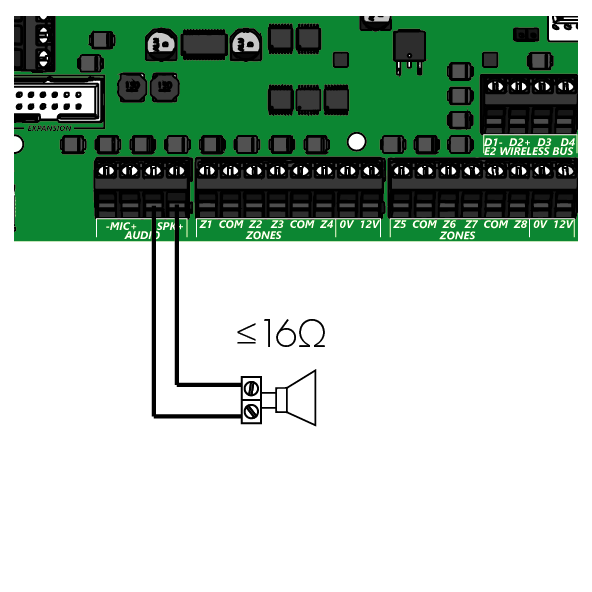
Terminals to wire in an external microphone (for future use) and an 10W, 16Ω AC extension speaker.
The zone terminals are in a Z1, COM configuration and can be wired in any of the following:
All keypads, proximity readers, wired and wireless expanders (both zone and output) are wired to these terminals.
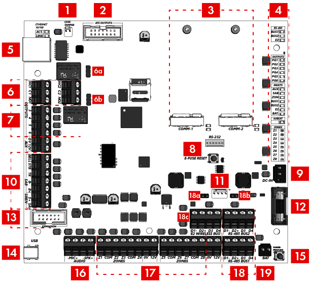
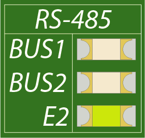
Above the RS485 terminals, each bus has its own EOB two-pin jumper header. If the RS485 bus needs a terminating resistor, the respective jumper is used to incorporate a 100Ω terminating resistor across the data line at the endstation. If this is used, a 100Ω resistor should be fitted at the furthest point of the bus across the D3 and D4 terminals.
For future development.
Connects the battery to the endstation.
For connection to 3rd party communication devices.
Most of the LED indicators are only active when the system is in engineer mode’. The only LEDs which are always active are the ‘Heartbeat’ LED and the communication LEDs.
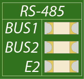
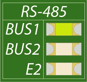
This section of LEDs show the status of the RS485 terminals. When a device is wired into these terminals and programmed to be active, the LED will illuminate.
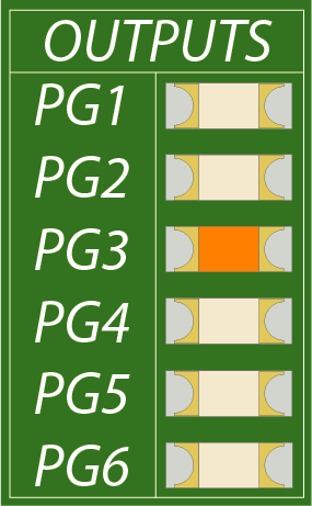
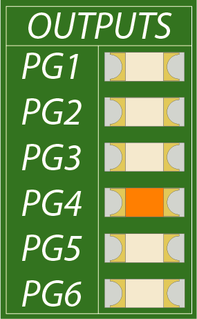
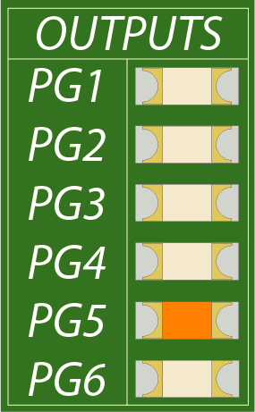
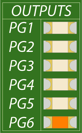
When the relevant output is triggered, the LED for that PGM output will illuminate and then extinguish when it returns to a quiescent state.
All fuses except the battery fuse are thermal fuses and can be reset by pressing and holding down the ‘E-FUSE RESET’ button in the middle of the PCB. They can also be reset in the Engineers menu in the option ENGINEER MAINTENANCE > Reset Efuses.
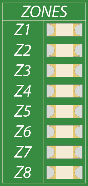
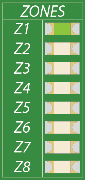
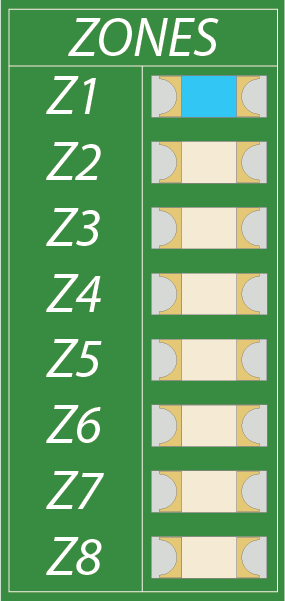
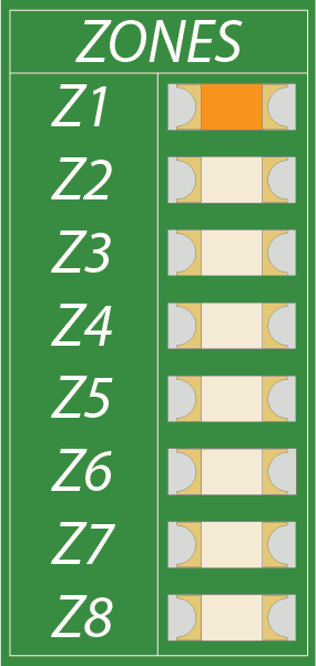
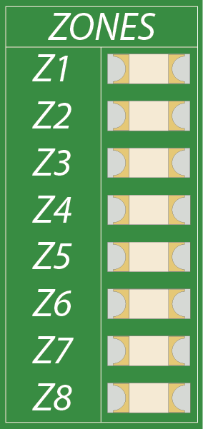
The zone LEDs are tri-colour to visually display all states that the zone can be in and not illuminated if the zone is not programmed. The below examples show the various states that the first zone can be in.
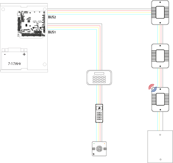
Example of peripherals wired on the RS485 buses.
| Cable Type | Screened Cable | Bus Range (m) | Daisy Chain Range (m) | Star Range (m) |
| 4 core alarm cable | Use when the bus is located near fragmented 230VAC main power line | 300 | 1000 For greater than 1000m range, standard isolated RS485 repeaters are required |
50 |
| 6 core alarm cable doubling D1 (0V) and D2 (12VDC) | 1000 | |||
| Twisted pair | 1000 |
The RS485 bus is used to communicate with peripherals that transfer and receive data. The main devices that are wired on to the RS485 bus are keypads, tag readers, zone expanders and PGM output expanders.
Each circuit is made up of one, two or three resistors depending on whether the circuit is being wired single end of line (SEOL), double end of line (DEOL) or triple end of line (3EOL). There are multiple terms that are used to describe the different states a circuit can be in, some of these are as follows:
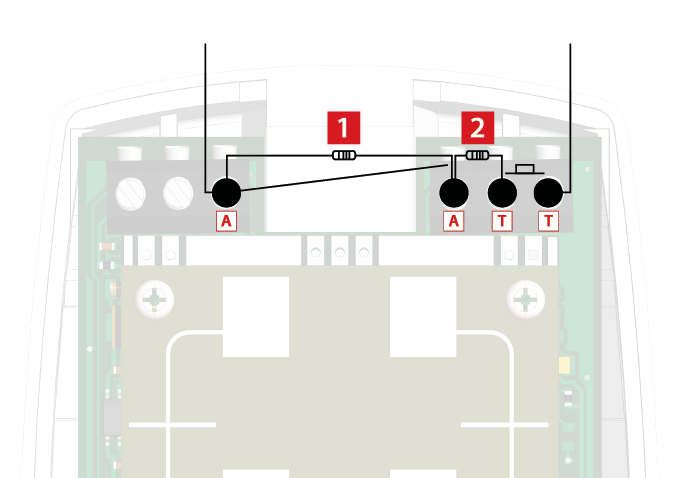
This circuit is comprised of two resistors.
A typical example of this is below, showing the circuit and the resistors wired in a DEOL configuration.
It is extremely important that the correct resistors are used when wiring the circuit. The EOL resistor is measured in the system all the time, when the detector goes into alarm, it adds this value to the EOL resistor . In the case of a masking scenario, the mask and alarm resistors are added to the EOL resistor allowing the control panel to distinguish four states – alarm, fault, mask and tamper. When selecting the resistors, it is vital to take notice of the range of each state and that, when added together, the resistance measured falls inside the range.
The below table shows the full range of resistances that can be selected in the control panel.
| Zone State Resistance Ranges | ||||
| Choice (Tamper/Alarm) | Normal | Alarm | Fault | Mask |
| 1k/1k | 0.8k – 1.2k | 1.6k – 2.4k | 2.5k – 6.9k | 7.0k – 10.6k |
| 2.2k/2.2k | 1.8k – 2.6k | 3.5k – 5.3k | 5.4k – 8.9k | 9.0k – 13.4k |
| 4.7k/6.8k | 3.8k – 5.6k | 9.2k – 14.8k | 19.9k – 18.7k | 18.8k – 22.6k |
| 6.8k/2.2k | 5.4k – 8.2k | 7.2k – 10.8k | 10.9k – 12.5k | 12.6k – 19.0k |
| 10k/10k | 8.0k – 12.0k | 16.0k – 24.0k | N/A | 24.1k – 32.2k |
| 3.74k/6.98k | 3.0k – 4.5k | 8.6k – 12.9k | 13.0k – 13.9k | 14.0k – 21.0k |
| 2.7k/2.7k | 2.2k – 3.2k | 4.3k – 6.5k | 6.6k – 9.7k | 9.8k – 14.6k |
| 4.7k/4.7k | 3.8k – 5.6k | 7.5k – 11.3k | 11.4k – 12.9k | 13.0k – 19.4k |
| 3.3k/4.7k | 2.6k – 4.0k | 6.4k – 9.6k | 9.7k – 11.7k | 11.8k – 17.8k |
| 3.3k/3.3k | 2.6k – 4.0k | 5.3k – 7.9k | 8.0k – 10.6k | 10.7k – 16.1k |
| 5.6k/5.6k | 4.5k – 6.7k | 9.0k – 13.4k | 13.5k – 14.3k | 14.4k – 12.6k |
| 2.2k/1.1k | 1.8k – 2.6k | 2.7k – 4.0k | 4.1k – 8.0k | 8.1k – 12.1k |
| 2.2k/4.7k (Default) | 1.8k – 2.6k | 5.5k – 8.3k | 8.4k – 10.9k | 11.0k – 16.4k |
Again, using the examples of 4.7k/2.2k resistance range. The tolerance table is as shown:
| Range Selected | Normal | Alarm | Fault | Masking | Tamper | |||||
| 4.7k/2k2 | from | to | from | to | from | to | from | to | from | to |
| 1.8 | 2.6 | 5.5 | 8.3 | 8.4 | 10.9 | 11.0 | 16.4 | <1.8 | >16.4 | |
The resistors that should be chosen
To wire in the 4.7k/2.2k resistor range, the resistors used should be a 2.2k for end of line, 4.7k for the alarm relay and 6.8k for the mask relay. The resistors will fall in to the ranges as follows when the zone changes states
The zones can also be wired in a double pole configuration; meaning either normally closed or normally open. If the zone is wired in this configuration, it must be programmed to operate in 0k/0k.
If the zones are wired in a normally open configuration, the zone needs programming on the system to reflect this. This programming can be altered in engineer menu PROGRAM ZONES > Choose Zone > Zone Attributes > Normally Open.
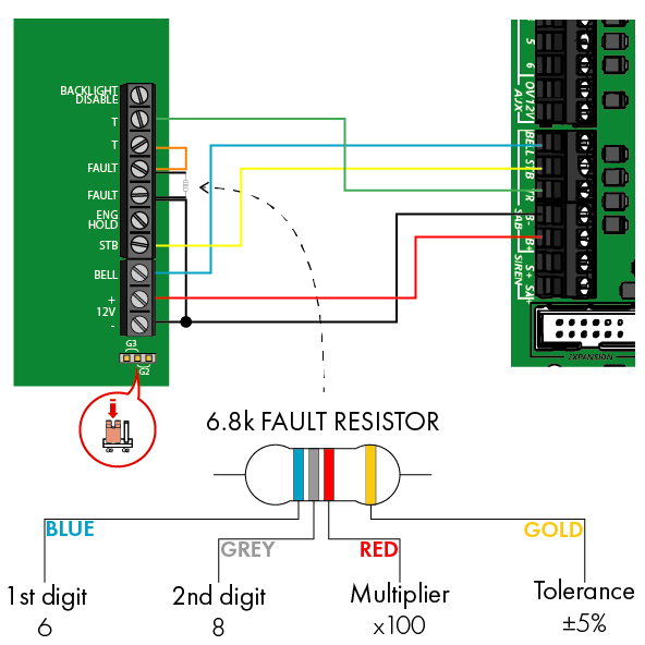
| PCB Marking | Terminal Function | Operation |
| BELL | Bell trigger | Negative applied output |
| STB | Strobe trigger | Negative applied output |
| TR | Tamper return | Negative input |
| B- | Bell negative | 0V auxiliary power for the bell |
| B+ | Bell positive | 12VDC auxiliary power for the bell |
| S+ | Siren trigger | Positive applied output |
| SA+ | Self-powered siren trigger | Positive removed output |
An extension speaker should be wired between the -SPK and SPK+ terminals and should not be greater than 16Ω. It does not need programming and will follow the tones programmed in the panel such as chime and entry/exit tones.
The panel should never be wired to a PC or laptop via USB.
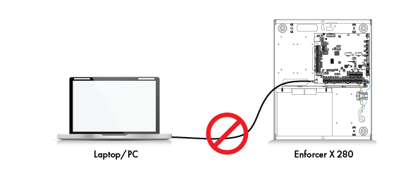
The USB port should only used to:
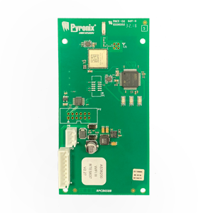
Partcode: ENFX-COMM-WIFI
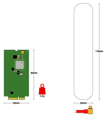
| Operating voltage | 9-16VDC |
| Operating current | 30mA |
| Storage temperature | -40°C to +80°C |
| Operating temperature | -10°C to +40°C |
Partcode: ENFX-COMM-4G/SIM
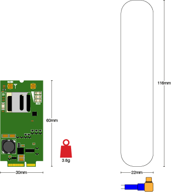
| Operating voltage | 9-16VDC |
| Operating current | 30mA |
| Storage temperature | -40°C to +80°C |
| Operating temperature | -10°C to +40°C |
See below the ATE ribbon, its default programming and colour order.

This is used to connect to a 3rd party signalling device and can be reprogrammed in the engineer menu.
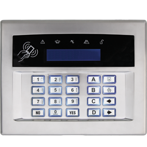 Arming Devices
 Communication Devices
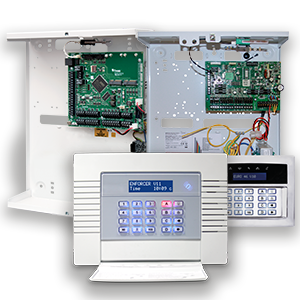 Control Panels
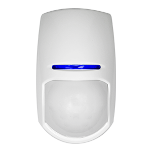 Detectors & Sensors
 Expanders
 International Products
 Legacy Products
 Smart Home Devices
 Software & Services
 Sounders & Bells
 Speech Diallers
 Wi-Fi Cameras